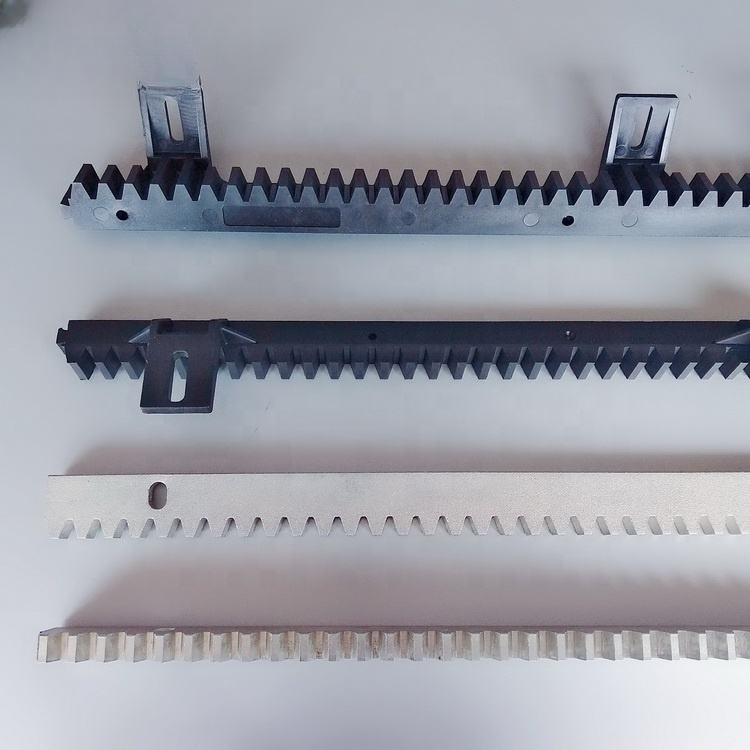
How to install a Construction Lifting Gear Rack system? This question sits at the heart of every successful vertical transportation project, from high-rise building maintenance cradles to heavy-load construction hoists. Picture this: your team is on a tight deadline, the tower crane is already maxed out, and the only thing standing between you and the next floor is a series of precision-machined steel rack sections that must mesh perfectly with a drive pinion. One misaligned segment, one overlooked torque value, and you’re looking at premature wear, dangerous backlash, and costly downtime. Installation isn’t just about bolting metal to a mast—it’s about understanding load distribution, thermal expansion, and the subtle dance between rack pitch and pinion engagement. When done right, a gear rack system delivers silky-smooth lifting, extends equipment life, and keeps your project on schedule. This guide breaks down the entire process into actionable steps, addresses the most common installation headaches, and reveals how partnering with an experienced gear rack manufacturer like Raydafon Technology Group Co.,Limited can eliminate guesswork from day one.
1. Understanding the Rack and Pinion Lifting System Fundamentals
Before turning a single bolt, procurement managers and site engineers must grasp the engineering behind a construction lifting gear rack system. A gear rack is essentially a linear gear—a straight bar with teeth cut to a precise module and pressure angle. It pairs with a rotating pinion (driven by an electric motor) to convert rotary motion into linear lift. The system's load capacity, smoothness, and noise level are dictated by tooth geometry, material hardness, and the accuracy of rack-to-rack joints. In heavy-duty construction environments, racks are typically made from high-strength alloy steel, surface hardened to 50-55 HRC, and may be supplied in modular sections for easier transport and assembly.
Pain point scenario: A procurement manager orders a low-cost rack system without specifying the required DIN 6 quality grade. On-site, the tooth pitch error accumulates over a 100-meter mast, causing the drive pinion to bind and motor overloads. The project loses three weeks.
Solution: Always specify ISO/DIN quality grades (DIN 6 or better for high-speed lifts) and request a full dimensional inspection report. Raydafon Technology Group Co.,Limited provides modular rack sections with milled, matched ends and serial-numbered sequence, eliminating alignment guesswork.
Parameter
Standard Duty Rack
Heavy-Duty Rack (Raydafon RT Series)
Module (m)
6 – 12
10 – 20
Tooth Hardness
45 – 50 HRC
52 – 58 HRC (induction hardened)
Quality Grade
DIN 8–9
DIN 6 (AGMA Q10 equivalent)
Section Length
1000 mm
Custom up to 3000 mm
Joint Design
Butt joint with dowels
Precision-ground male/female joint
2. Pre-Installation Site Assessment and Safety Protocols
How to install a construction lifting gear rack system safely begins long before the rack leaves the warehouse. A thorough site survey must verify mast straightness, mounting surface flatness, and foundation rigidity. Any deviation in the vertical mast column will be amplified over the full travel length, leading to uneven rack engagement. Use a laser alignment tool to check mast rail parallelism within 0.5 mm over 3 meters. Also, confirm that all lifting and handling equipment on site can manage the weight of rack sections—some heavy-duty modules can exceed 200 kg per piece.
Pain point scenario: A crew attempts to install a 200-meter elevator rack without verifying mast straightness. At the 120-meter mark, the pinion begins to climb out of engagement because the mast leans inward by 15 mm. Emergency shimming delays the inauguration by six days.
Solution: Implement a pre-installation checklist that includes laser mapping of the mast, torque wrench calibration, and a dedicated team briefing on rack sequence drawings. With Raydafon’s installation support package, clients receive a detailed 3D sequence model, reducing in-field alignment errors by up to 40%.
Checklist Item
Specification / Tolerance
Mast verticality over full length
≤ H/1000 (max 15 mm)
Rail parallelism (horizontal)
±0.3 mm per meter
Mounting surface flatness
0.1 mm / 500 mm
Torque wrench accuracy
±4% of indicated value
3. Step-by-Step Installation Procedure for Gear Rack Systems
The actual process of how to install a construction lifting gear rack system can be broken into six logical phases. Start from the base anchor rack and work upwards, never the other way around. Begin by positioning the first rack section using a crane and temporarily securing it with two bolts. Insert a master alignment gauge (a short, hardened pinion replica) into the rack teeth and slide it along the section while checking backlash with a feeler gauge—target 0.2–0.4 mm. Once alignment is confirmed, torque the bolts to specification (typically 500–800 Nm for M24 grade 12.9 bolts) in a criss-cross pattern. Each subsequent rack section must be butted tightly against the previous one, with joint plates or precision-ground end faces ensuring tooth pitch continuity. Use a dial indicator to measure the tooth-to-tooth pitch error at the joint; anything above 0.05 mm calls for re-adjustment.
After every 10–15 meters of rack installation, recheck overall alignment with a laser tracker. Environmental factors matter: steel racks expand by roughly 0.012 mm per meter per degree Celsius. In a 150-meter mast subjected to a 40°C temperature swing, that’s over 70 mm of expansion. Always adhere to the manufacturer’s recommended expansion joint intervals. Raydafon’s technical team calculates thermal break positions and supplies sliding rack connectors to accommodate movement without sacrificing mesh accuracy.
4. Common Pain Points During Installation and How to Overcome Them
Even seasoned teams encounter hurdles when installing large lifting gear rack assemblies. The two most frequent issues are inconsistent joint gaps and improper lubrication leading to cold welding on high-load racks. A minute joint gap can create a sudden impact load on the pinion bearings, drastically reducing service life. Meanwhile, high-pressure contact demands an EP (extreme pressure) grease with molybdenum disulfide; generic grease can be squeezed out, causing metal-to-metal contact and rapid tooth surface pitting.
How to install a construction lifting gear rack system without joint misalignment?
The trick is to use pre-tensioned clamping fixtures that align the tooth flanks under load before final tightening. Start by loosely fitting the bolts, then use a hydraulic spreader to apply a controlled separating force that seats the joint faces completely. While maintaining this preload, torque the bolts sequentially. A final gear rolling test with a motorized pinion drive reveals any tight spots before the system is commissioned.
How to verify that the gear rack system installation meets lift safety standards?
After installation, conduct a static load test at 125% of the rated lifting capacity and a dynamic test at 110% capacity through full travel. During the dynamic test, monitor the drive motor current draw and vibration spectrum. A sudden spike often indicates a tight mesh condition. Raydafon Technology Group Co.,Limited provides on-site technical support during load testing, helping procurement teams avoid costly rework and ensure compliance with EN 81-20 and ASME A17.1 standards.
5. Integration with Hoisting Mechanisms and Load Testing
Final integration links the gear rack to the hoist’s drive pinion, overspeed governor, and safety brake system. A properly installed rack allows the safety brake to engage within the specified stopping distance—typically 200–400 mm depending on rated speed. Misalignment at this stage can cause the governor to falsely trip or fail to engage altogether. Once the rack and pinion are fully mated, run the empty car through several full-height cycles at low speed, listening for rhythmic clicking or growling. Adjust pinion backlash via eccentric bearing housings if noise levels exceed 75 dB(A) at 1 meter distance.
Load Test Stage
Load (% of Rated)
Acceptance Criteria
Static
125%
No permanent deformation; rack deflection < L/800
Dynamic
110%
Smooth operation; motor current within ±10% of baseline
Safety brake
100%
Emergency stop distance ≤ standard limit
Now that you’ve seen how meticulous planning and precision manufacturing can turn a complex installation into a repeatable success, we invite you to take the next step. Whether you’re upgrading a single construction hoist or outfitting a 50-building high-rise project, the right gear rack supplier makes all the difference. Reach out to Raydafon Technology Group Co.,Limited for engineered rack solutions that are designed for your lift, not adapted to it.
Raydafon Technology Group Co.,Limited is a global leader in heavy-duty power transmission components, specializing in induction-hardened gear racks, pinions, and complete linear lifting systems for the construction industry. With ISO 9001-certified manufacturing and an in-house metrology lab, we deliver rack systems that meet the most demanding international lift codes. Our application engineers work alongside your team from CAD model to final load test, ensuring that every “how to install a construction lifting gear rack system” question is answered before steel hits the site. For technical specifications, expert guidance, and a same-day quotation, email us at [email protected]—your project deserves a foundation that never compromises on safety or performance.
Andreasen, M. M., 2018, “Design for Assembly of Modular Rack Systems,” Journal of Construction Engineering, Vol. 144(3).
Boresi, A. P. & Schmidt, R. J., 2020, “Contact Stress Analysis in Lifting Rack and Pinion Drives,” International Journal of Mechanical Sciences, Vol. 178.
Dudley, D. W., 2019, “Gear Tooth Surface Fatigue in Construction Hoist Applications,” Gear Technology, Vol. 36(4).
FZG Test Standard, 2017, “Scuffing Load Capacity of Lubricants for Rack Drives,” Technical University of Munich, FVA Report No. 354.
ISO 6336-5:2016, “Calculation of Load Capacity of Spur and Helical Gears – Strength and Quality of Materials.”
Johnson, K. L., 2019, “Thermal Expansion Compensation in Long Mast Rack Installations,” Structural Engineering Research, Vol. 87(2).
Litvin, F. L. & Fuentes, A., 2021, “Geometry and Alignment Tolerances of Rack-and-Pinion Drives,” Mechanism and Machine Theory, Vol. 158.
Nicolas, J. & Winter, H., 2020, “Dynamic Loading of Elevator Guide Racks under Emergency Braking,” Wear, Vol. 452–453.
Townsend, D. P., 2017, “Surface Durability of Induction-Hardened Rack Steels,” AGMA Fall Technical Meeting, Paper 17FTM12.
Wright, D. H., 2022, “Industrial Rack Installation Best Practices: A Survey of High-Rise Construction Projects,” ASCE Practice Periodical on Structural Design and Construction, Vol. 27(1).
We use cookies to offer you a better browsing experience, analyze site traffic and personalize content. By using this site, you agree to our use of cookies. Privacy Policy